We'll check out how to program an AVR 8-bit Microcontroller(Attiny, Atmega) in DIP package using the AVRISP mkII programmer and AVR Studio 4. Cool stuff here is that we won't require programming boards such as STK500 or STK600 (which are expensive boards), we'll use instead one breadboard and we'll make the connections ourselves, it's pretty easy to do so. We'll divide this tutorial in two parts: setting software and setting hardware.
Setting up Software
-AVR Studio 4 (download it from here)
-WINAVR (download it from here)
The main program that we will be using is AVR Studio 4. Altough AVR Studio 5 is available, it stills presents considerably bugs, so it's better using the old version, which is way more stable and very efficient. Windows 7 and Windows XP SP3 are highly recommended.
When you install AVR Studio, the installer will ask you to install Jungo software, install it, you need Jungo drivers for the AVRISP mkII.
After installing AVR Studio, you must install WINAVR.

AVR Studio 4
Now, we have to open AVR Studio, before programming our microcontroller we need a program, so we'll make one.
We need to make click on Project/New Project in the Main Toolbar, a new window will appear and we need to make click on AVR GCC, now we have to put a name to our project, let's call it "Blink", click on "Create initial file" and "Create folder" boxes. On location you can select a folder of your preference. After all this setup click on next.

We select on Debug Platform "AVR Simulator", AVRISP mkII is a PROGRAMMER not a DEBUGGER. Now we have to select which device we'll be programming with. In my case I'll be using Attiny13A. We now click on Finish.

We now have something like this on main screen:

We now have everything we need to make our code. We just have to write on our "Blink.c" file , we have our editor open as you can see on the image. As the name says, we'll just make our program to blink one led. Here's the code:
//cpu main clock frequency, needed for delay library
//check datasheet for further information
#define F_CPU 1200000 //9.6Mhz/8 = 1.2Mhz
#include <avr/io.h>
#include <util/delay.h>
int main(){
DDRB = 0x01; //PB0 is set to output
while(1){ //Infinite loop
PORTB ^= 0x01; //Change PB0 bit, 0 to 1, 1 to 0
_delay_ms(1000); //One second delay
}
return 0;
}
In our code we include "avr/io.h" library in order to use IO registers (DDRB and PORTB by example). "util/delay.h" is required in order to use "_delay_ms()" function.
F_CPU is not a constant for all AVR microcontrollers, you must consult datasheet for further information (see System Clock and Clock Options on datasheet). By example, Atmega328 is factory programmed to operate at 1Mhz, using internal RC Oscillator.
We click on "Build" on the Main Toolbar after our code is correctly pasted on the editor, and everything should go fine (check build results for solutions if error appeared), you should see on the console the file's size (about 70 bytes with Attiny13A).
We're almost done with software, but now we need to set up our hardware.
Setting up Hardware
The hardware stuff consists of making conections on our breadboard, our AVRISP mkII programmer has 6 pins(these 6 pins are for ISP connection and programming) as described here:


Pin1 is found on the Red side of the connector, also you can find Pin1 by checking on the female connector an arrow signaling it (Please refer to this document for further information).

In order to connect our AVRISP mkII to our breadboard, we'll need to connect wires to its female headers, or use male headers and make a custom board(what I did), I bought a pre-made PCB board with lots of holes of .1" spacement,our breadboard uses the same pin spacement, so it was easy to solder 6 male headers for the programmer, and another 6 to connect the board to the protoboard:


Below you can check out pin configurations for Attiny13A (refer to Atmel' site for the datasheet if further information is required):

If you compare Attiny13A pins with AVRISP mkII pins, you'll find that they have 4 pins with same name (besides GND and VCC), same named pins must be connected in order to succesfully program our microcontroller. (If using another AVR microcontroller you must consult its datasheet to find which pins are same named as our programmer for making connections).
Before starting making our connections, we must connect our programmer to our computer, using and USB cable, you should see AVRISP leds blinking. After connecting, you should see a message displaying that our hardware is correctly installed. If encountering trouble please refer to this previously posted document.
Make sure to unpower programmer before continuing.
The next image shows us my connection on a breadboard, the red board is simply my power supply that's draining power from my computer USB, you can also connect AA batteries in series in order to get 3V. Power supply is 5V, most AVR 8-bit operate at 1.8 - 5.5V range, but it's always a good idea to check out datasheet. I connected one 10k Ohm resistor to pin 1 and to 5V line, this resistor must always be on RESET pin even while not programming mode. We can observe I left six wires connected to nothing, this six wires will be connected to the AVRISP mkII (connect wires or make a little board).
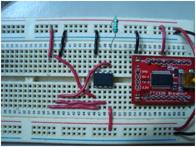
In next picture we have PINs names and their connection. Black wires all are connected to GND line. And only Red wires connected to Red line are VCC.

My custom board connections:


Now, we must power up our programmer again (connect it to computer) and after a while a red led should be blinking(if not don't worry, sometimes happens), red led means we have a wrong connection, in this case it's okay because we haven't connected our microcontroller's supply power, so connect it. Now red led should change to green. If the led didn't change, quickly unplug everything and make sure you connected everything accorded here.
We are now ready to program our microcontroller, return to AVR Studio and click on "Con" icon

A window should appear like next one, we must click on AVRISP mkII on Platform and USB on Port, then click on Connect (between next steps one window could appear telling you that there is available new firmware for your programmer, if so, update your firmware!).

After a couple of seconds next window should appear. On Device and Signature Bytes we must choose our microcontroller (Attiny13A on this example). After that we must click on Settings button and select 125Khz ISP Frequency. In order to program with AVRISP mkII , programmer must be operating at: (F_CPU) / 4, minimum, which is in my case 1.2Mhz/4 = 300 khz, however it's more recommended programing at : (F_CPU)/8, so going safe would be to operate at 150khz, better set it to 125 khz because it's one standard frequency of our programmer. Now we must click on Read Signature, it should appear something like the picture above, no errors, only OK! on the console, and a message above some hexadecimal numbers saying "Signature matches selected device". Here we may find many errors ocurring... one we mentioned earlier(most common) is bad wiring, check programmer's leds. Bad frequency setting, try lowering frequency. Wrong device selected on combobox. The worst thing here would be to discover that our microcontroller is burned...Please refere to troubleshooting of this document.

After reading signature and all those settings, its finally time to program. First, we should click on "Erase device", console should inform us everything went fine as displayed on image. Now on "Input HEX file" textbox we must search our folder for our HEX file, by example : "/Blink/default/Blink.hex", now we only have to program our board by clicking on program. If no errors were displayed, we did it, we programmed our microcontroller. Unplug microcotroller power, and disconnect programmer.

Finally, we disconnect all wires connected to our programmer, and we connect one led in series with a resistor on PB0 (pin 5 of Attiny13A). We only leave one resistor on RESET pin, GND and VCC connections besides the led pin. If we power again our board, we should see our led blink every second.

The cool stuff of doing all this without one programming board is that we can now make our own programming boards understanding which pins are used for programming. We will also be able to adapt final project boards with connections for infield programming. By example(and the best) we have Arduino board, this board has an ISP connection for use with the AVRISP mkII to program the Arduino's board microcontroller(an AVR Atmega).
Will follow this and hopefully it will work for me too.
ResponderEliminarThanks for a great article!
ResponderEliminarCould it be that the SCK and RESET labels are confused in this image:
http://1.bp.blogspot.com/-Y3_Mdztw2v8/TjCIBvSqX1I/AAAAAAAAABI/6G0tHEbHWaE/s1600/imagen12.jpg
?
********************************************************
ResponderEliminar----BUY ELECTRONIC COMPONENTS AND GADGETS ONLINE AT-----
............ www.kimaginations.com .................
===============LOWEST PRICE IN INDIA ===================
(Get Exciting Offers and Discounts)
(ROBOTICS,EMBEDDED,VLSI KITS,MATERIALS AND PROJECTS)
USE COUPON CODE : KI100DISC
*GET Rs. 100 /- OFF ON PURCHASE
********************************************************
*T&C Apply
yes, in the pic:
ResponderEliminarhttp://1.bp.blogspot.com/-Y3_Mdztw2v8/TjCIBvSqX1I/AAAAAAAAABI/6G0tHEbHWaE/s1600/imagen12.jpg
the 3 in down right corner should be: Reset - sck - miso